Home › CMKE exam questions with answers (Poland) › F1 Electrical, electronic and control engineering — ETO (CMKE, Poland) › The circuit described in the picture is supplied from a dire…
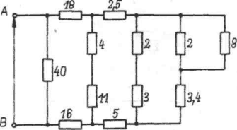
The circuit described in the picture is supplied from a direct voltage source of value U = 220 V. The numbers denote resistance in ohms. Current received from the source equals:
A 1 A, B 11 A, ✓ C 2 A, D 20 A. Correct answer: B) 11 A,
Take the full test: F1 Electrical, electronic and control engineering — ETO (CMKE, Poland) → Random exam test generator, free, no registration More questions from this test
In a passive circuit there are given resistances and the current flowing through resistance R4. Supply voltage equals: In a circuit presented in the picture, the current intensity I2=2 A. Resistance values: R1 = 3 Ω, R2 = 18 Ω, R3 = 3 Ω, R4 = 6 Ω. Equivalent resistance of the circuit and supply voltage equal: Voltage divider made up of R1 and R2 resistors was supplied with voltage of U = 200 V. Given: R1 = 100 Ω, R2 = R3 = 300 Ω. Voltage values U2 at the output of the divider with open and closed W switch equal: Electrical load with resistance of Rodb = 40 Ω is supplied from a potentiometer (Rp = 80 Ω), whose terminals are connected to voltage of U = 120V Values of electrical load current and voltage, assuming the potentiometer slider is in the middle position (Rg = Rd) are equal to: In a circuit presented in the picture, electromotive forces equal E1 = 100 V, E2 = 120 V, resistances R1 = 10 Ω, R2 = 40 Ω. Current I has the following value: Coulomb’s law can be written using the following formula: Q Q F = k 1 2 Value of electric field intensity in a given point is determined by the following function: Equivalent capacity Cz for two condensers with capacities of C1 and C2 in a parallel connection may be calculated using the formula Question list: F1 Electrical, electronic and control engineering — ETO (CMKE, Poland)
 SeaQuiz